|
|
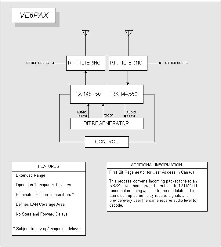
In 1989 I decided to put together a 1200 baud duplex (repeater) bit regenerator for packet radio. It was to regenerate packet tones in real time unlike a digi-peater that uses a TNC and a simplex radio. Here is a block diagram of the repeater.
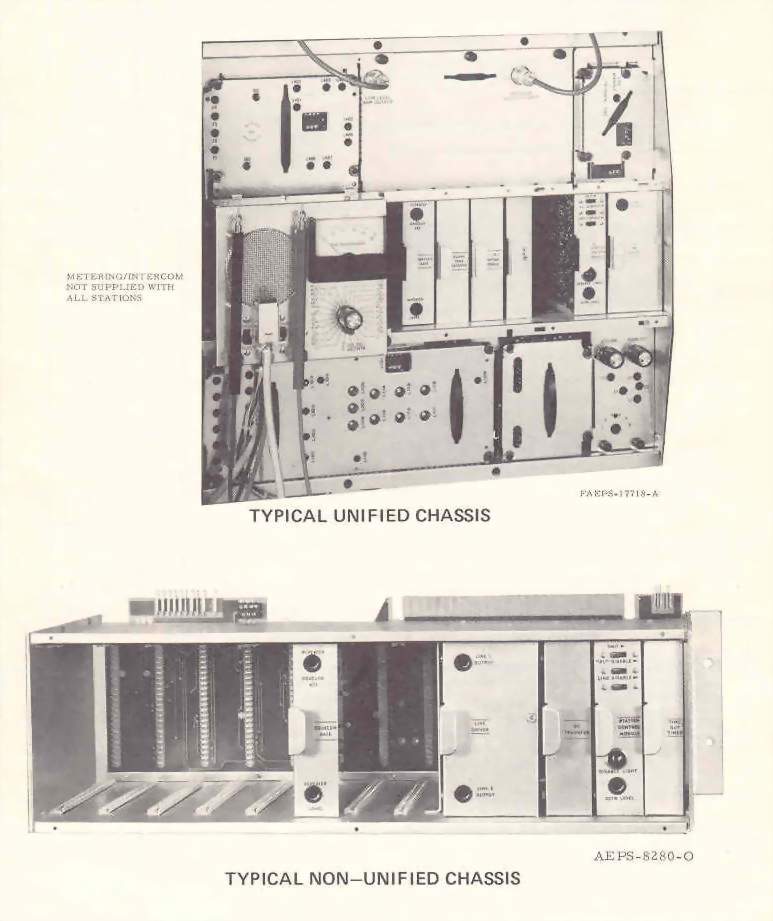
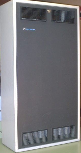
The repeater was an experiment as at the time I was unaware of any other existing. I acquired a non-unified Motorola Micor repeater that was taken out of service for being unreliable. In fairness to the Micor, it was not installed in a very good environment. The Micor was a VHF high split (162 to 174 MHz) radio that had to be brought down to 145 MHz. Anyone who has changed the operating frequency of a Micor to work well out of it designed operating range knows what is involved. Another problem was that it did not work when I got it.
The Micor was covered with greasy carbon dust from nearby elevator motors when it was removed from commercial service. The circuit boards and back plane were removed and cleaned up in the laundry room sink. The RF power amplifier was repaired and parts changed to work at 145 MHz. Parts were also changed on the exciter board and receiver including the replacement of the receiver helical resonator coils.
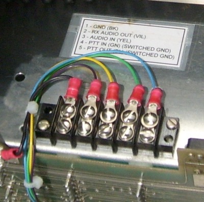
The packet tones were regenerated using a General Data Comm 202 modem model GDC 202-T looped back at the RS232 level. This particular modem had true data carrier detect and the DCD was used to key the transmitter. All 202 modems are not the same, for example, the Motorola (MDS) 202T modem will produce a DCD with just receiver (un-squelch) noise. Un-squelched audio is required to speed up the transmitter key-up time.
I used a Morse ID card from a Motorola MSR2000 station and configured it to ID every 30 minutes. It was also to be used for some basic troubleshooting if required. The ID’s in these cards were programmed in using a fusible link prom. Fortunately 2 call signs can be programmed into each prom (note) and if an old card became available it would almost always have room for another call sign.
Basic "over the air" control of the repeater was used. A tone module built for this type of station and originally design to be operated by wireline was modified to work over the air. Its function was simply to enable or disable the transmitter. Care was take so that the transmitter would power up enabled should the AC power fail and return. Enabling the transmitter remotely would force an ID indicating that the transmitter was indeed enabled.
A time out timer card was used in an unusual way. Should any continuous signal (packet or not) be present at the repeater input for more than a certain period of time (jumper selectable) the timer card would time out and force a Morse ID and the card would then reset. It would not disable the transmitter. If the signal persisted, the ID would then again be initiated. The repeater would then ID frequently under this condition. The repeater does not pass audio like a regular ham repeater. It would only regenerate valid packet tones. If there were an interfering signal on the input it would not be heard unless it was a valid packet tone and in that case the repeater would regenerate it. This approach would still allow the repeater to work with degraded performance and also indicate that there was an interfering signal on the input.
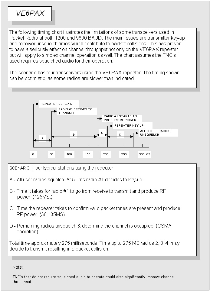
A goal was to reduce the transmitter key-up time to as little as practical. This was to help reduce packet collisions. One of two things would happen during a packet collision. Neither signal would get through (assuming only 2 stations were involved) or the station with a much strong signal would get through. Packet radio works using the Carrier Sense Multiple Access approach, that is, if a station is transmitting every other station on frequency waits their turn. If a station thinks the channel is clear because the repeater is in the process of still keying up, a packet collision may occur. See the attached timing chart. I settled on a 30 to 35 millisecond key-up time. Fifteen milliseconds of this were caused by the modem determining if valid packet tones were present and producing DCD. I experimented by just keying the RF power amplifier. This virtually eliminated the station key up delay and just leaving the modem DCD delay. A problem was that the exciter signal would leak through the PA and produce a –30 dBm signal at the antenna output, not much of a signal but it was still there.
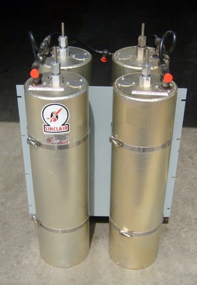
The repeater was to go on to a commercial site that shared antennas with different users. I used Sinclair C2037 multicouplers for RF filtering, one for the transmitter and one for the receiver. They consist of 4-quarter wave cavities each. The multicouplers I had were originally tuned around 165 MHz and I built up new cable harnesses to be compatible with 145 MHz. With this amount of filtering the repeater could have been installed on one antenna but 2 were available and I used one antenna for transmit and the other for receive.
The repeater was in operation for fourteen and a half years and proved to be very reliable and had high usage in the early years. After a number of years, the traditional usage of packet radio fell off and so did the activity on the repeater. Simplex backbones were being replaced by APRS nodes and packet radio BBS’s got little use. By 2004 the main use of the repeater was for a DX Cluster. A six-month noticed was given that the repeater was to be taken off the air. I cleared up loose ends by tuning up and provided a high quality commercial radio for the DX cluster owner who installed the radio in a good location.
The VE6PAX effort did not go unnoticed. The Calgary Amateur Radio Association acknowledged the effort with a Merit Award and a Letter of Appreciation.
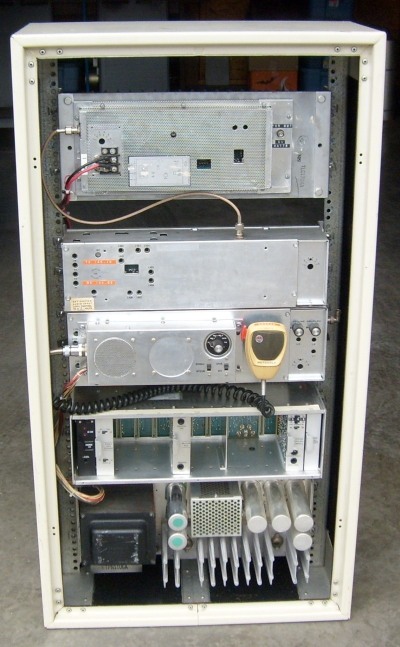
Photos of the VE6PAX repeater can be seen elsewhere on this website.
UPDATE: February 24, 2008
We removed the VE6PAX repeater along with the Sinclair C2037 multicouplers from the commercial site it was on in the summer of 2007. I re-installed the repeater components in the original Motorola Micor cabinet and converted it back to a voice repeater. Interfacing circuitry was added in the event that it may become part of some future linking project. The repeater works very well and was operational temporarily at my home location on 145.150 MHz -0.600 to confirm it reliability. At the same time I built up what is essentially a Sinclair Q202G duplexer using 4 Sinclair FQ cavity filters I had on hand. I used a Sinclair rack panel and mounting components when assembling the duplexer. At this time the repeater is not in service.|
|
|
|
|