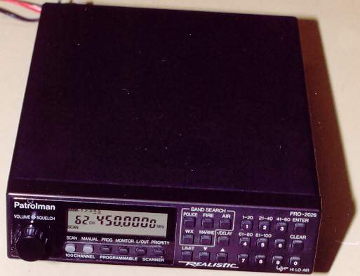
I bought the scanner when it first came out and was the first scanner I owned. It was advertised as a mobile scanner but I had planned to use it mostly in the ham shack. Initially I was disappointed with the performance, specifically the intermod and image rejection performance. Intermod was especially noticeable on VHF and the poor image rejection performance was everywhere. Indications were that the scanner had virtually no front-end selectivity. It is interesting that the operator’s manual makes a point of some minor receiver spurs but make no mention of a serious image problem. On the plus side, the scanner had good audio.
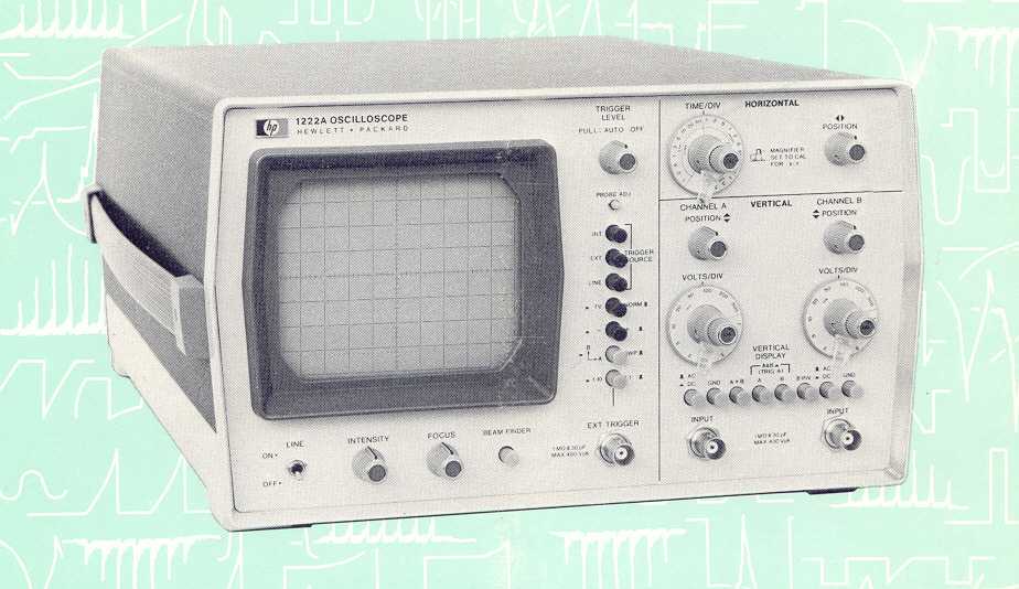
I was seriously thinking of returning it to Radio Shack when I though it may make a usable piece of test equipment. Since it did not have any front-end selectivity, gain may be reasonably flat across large parts of the different bands it covered. See using the Realistic PRO-2026 for Tuning Cavity Filters write up on this website. Also, since the audio sounded very good it likely had reasonably low distortion and being a fairly low cost scanner the IF selectivity was probably not very narrow. I looked into the possibility of using it in conjunction with my HP oscilloscope to make a deviation monitor. The scanner did not have an internal battery to maintain the memory. A wire was to be connected to an unswitched +12 volt point in the vehicle for the backup. What I was planning to do was to install a 9 volt battery with some isolation diodes in a small box located outside the scanner for memory back up. The box could also be used to contain the parts for the interface between the scanner and the scope.
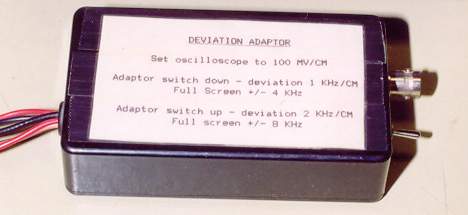
The scanner did not come with a schematic with the operator manual. I had to poke around the discriminator area of the scanner with a scope to find a suitable spot to extract non de-emphasized audio. I did find a suitable spot and tests indicated that it would be worth while to continue assembling the interface between the scanner and the scope. Also, indications were that the scanner's PLL phase noise was low. The scope I was to use to indicate deviation is calibrated in centimeters with a total of 8 centimeters full scale vertically. I decided to calibrate the interface box to indicate 0 to +/- 4 kHz deviation and 0 to +/- 8 kHz deviation. One centimeter of vertical deflection on the scope could be either indicate 1 or 2 kHz deviation using a toggle switch on the interface box to select between the two. A high quality oscilloscope should not be a requirement as we are only dealing with audio frequencies. An HF station monitor oscilloscope may be suitable or possibly a sound card scope but I have not tried this. Initially I used a commercial service monitor to calibrate the deviation monitor interface box but later used the Bessel zero method. Interestingly enough, the accuracy of this deviation monitor appears to be as good as some commercial units under the conditions hams would likely use it, that is setting repeater repeat deviation, checking CTCSS (PL) tones, adjusting for maximum deviation on VHF/UHF FM rigs etc. Where it falls off is with the combination of high deviation and high modulating frequencies. Here is a calibration table for this particular scanner created using the Bessel zero method for calibration.
The interface box does not consist of much more than a few parts including a couple of potentiometers and a switch. If anyone wants to try this do so at your own risk. It is possible to cause damage to the scanner if not done right.
You will need a good regulated power supply to power the scanner. A 12 volt cube that you plug into the wall is OK for normal operation of the scanner but not if it is used as a deviation monitor as it will likely introduce ac hum and vertical jitter on the scope waveform. There may also be some PPL jitter. In my case it was quite low.
There are likely other scanners available that are suitable for this application.